- LIVE HELP IS

Case Study 6 – Multiple Response Optimization and Practical Tolerance Design
Introduction: Optimizing Low Pass RC Filter
The passive low pass RC (Resistor Capacitor) filter network shown below has been analyzed in several papers (see Case Study 6 References) and will be used to demonstrate how DiscoverSim allows you to easily solve the difficult problems of multiple response optimization for parameter design and practical tolerance design.
The design approaches presented in the reference papers and books include: Axiomatic Design (Suh, El-Haik), Taguchi Methods (Filippone), Analytical Design for Six Sigma (Ferryanto), and Integrated Parameter and Tolerance Design using Factorial Design of Experiments and Loss Function (Feng).
Acknowledgements and thanks to Dr. Eric Maass and Andrew Sleeper for their valuable feedback on this case study.
The RC filter network to be designed (C, R1 and R2) suppresses the high-frequency carrier signal and passes only the desired low-frequency displacement signal from the strain-gage transducer to the recorder with a galvanometer/light-beam deflection indicator (El-Haik, Feng). (Light beam galvanometers have been replaced with digital oscilloscopes, but they still have practical application today in laser scanning systems).
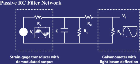
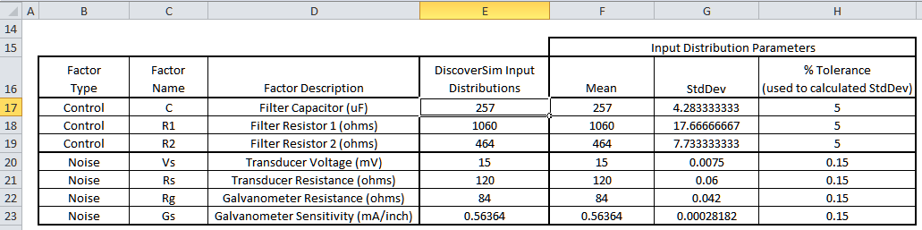
Vs is the demodulated transducer voltage and Rs is the transducer resistance (impedance). Rg is the galvanometer terminal resistance. Vo is the galvanometer output voltage which produces the deflection displacement. One of the output responses of interest, galvanometer full scale deflection D, is a function of Vo, Rg, and the galvanometer sensitivity Gs. The values for Vs, Rs, Rg, and Gs are determined by the transducer and galvanometer vendors and are therefore considered as noise factors. We will use the nominal and tolerance values given by Feng and Filippone for the noise factors: Vs = 15 mV; Rs = 120 ohms; Rg = 84 ohms; Gs = 0.56364 mA/inch. All tolerance values are ± 0.15%. We will model these noise factors using a normal distribution with mean set to the nominal value and standard deviation calculated as nominal*(tolerance/100)/3 = nominal*0.0015/3.
Capacitor C, and resistors R1, R2 are the components of the passive filter network. These are the design control factors of interest in this study. The mean values for C, R1, and R2 will be varied using parameter design optimization to meet the required output specifications with minimal variation. Tolerances on these components are also noise factors that contribute to variability in the output but we can select those tolerance values that are required to give us the desired performance. The starting nominal and tolerance values will be those given in Feng and Filippone: C = 257 uF, R1 = 1060 ohms, and R2 = 464 ohms with tolerance = 5% for each. As with the noise factors, we will model the control factors using a normal distribution with mean initially set to the nominal value and standard deviation initially set to nominal*(tolerance/100)/3 = nominal*0.05/3.
The output responses of interest are full scale deflection D and filter cut-off frequency F. The equations (derived from Kirchhoff's Current Law) are given as:
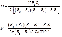
Note: Resistors R1 and R2 affect both output responses, and capacitor C only affects the cut-off frequency F.
The target value for Deflection D is 3.0 inches. We will use ± 1% as the tolerance for D so the lower specification limit LSLD = 2.97 and upper specification limit USLD = 3.03. The target value for Filter Cut-Off Frequency F is 6.84 Hz. We will use ± 5% as the tolerance for F so LSLF = 6.498 and USLF = 7.182. Process Capability indices will be used to measure the quality of each output response, but optimization will be performed by minimizing the multiple output metric “Weighted Sum of Mean Squared Error (MSE)”, also known as the loss function:
MSE (Loss) = WeightD[(MeanD – TargetD)2 + StdDevD2] + WeightF[(MeanF – TargetF)2 + StdDevF2]
The control and noise factor settings are summarized in the table below:
The minimum and maximum mean values used for parameter optimization of the control factors are the values from Filippone for the Taguchi Inner Array:
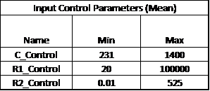
(Note that if we did not have the above nominal mean values for control factors available as starting values, we would use the mid-point of the minimum/maximum to start the optimization. The final optimization result would be the same in either case because the optimizer is global not local.)
We will also consider standard component availability and cost in this case study (source: electronic component supplier www.mouser.com). One practical concern will be the capacitor. Capacitors larger than 230 uF will typically be electrolytic with a 20% tolerance or more, so specifying a tolerance of 5% or less will significantly increase the component cost.
In this study we will use DiscoverSim to help us answer the following questions:
- What are the predicted process capability indices with the published nominal settings?
- What are the predicted process capability indices after parameter optimization? How do they compare to the baseline results above?
- What are the key control factors (Xs) that influence Deflection D and Frequency F?
- What standard components are available that are close to the optimal values obtained from parameter design?
- What tolerances are available for those standard components? Can we minimize the component cost and achieve a Six Sigma quality design?
| Summary of DiscoverSim Features Demonstrated in Case Study 6: |
|
Define, Measure, Analyze, Improve, Control


Simulate, Optimize,
Realize

Web Demos
Our CTO and Co-Founder, John Noguera, regularly hosts free Web Demos featuring SigmaXL and DiscoverSim
Click here to view some now!
Contact Us
Phone: 1.888.SigmaXL (744.6295)
Support: Support@SigmaXL.com
Sales: Sales@SigmaXL.com
Information: Information@SigmaXL.com


